Dante: Network Topologies
Network technology has now become indispensable in modern audio systems. In the last few years there has really not been a project where I did not come into contact with Audio over IP in some way. Nowadays, Dante in particular is included in every new installation or is retrofitted in existing systems. The entire infrastructure of a house is partly based on Dante as the communication protocol for audio data. Analog connections exist almost only for the first 10 meters, from the microphone to the nearest A/D converter.
In the meantime, I have found a great deal of pleasure in IT networks and have made it my goal to shed some light on interested sound and IT colleagues.

In addition to the choice of the right switches, the topology in particular is decisive for the performance and operational reliability of an IT network. And so I would like to present some Dante network structures as an example.
SEPARATION OF PRIMARY AND SECONDARY NETWORK
As the inventor of Dante transmission, Audinate has already thought of a mature redundancy. Most devices have two network sockets for this: Primary and Secondary. The audio signal is always sent simultaneously over both networks. The Dante receiver can therefore automatically switch from the primary to the secondary signal in the event of a fault.
It is necessary that two separate networks are set up for this. It is not possible to route both network sockets of a device to the receiver via the same network.

Since we cannot rule out the possibility that a switch or a cable connection will fail one day, the use of both networks is absolutely common in the professional audio sector. The following Dante topologies therefore always assume two separate parallel networks.
Example Topologies
No Switch = Daisy Chain

The easiest way to connect Dante devices with one another is to daisy chain them without a switch. Except for a short functional test, I would not recommend this method in a professional environment. The failure of a device has the consequence that the entire chain is interrupted. And unfortunately this also happens when you restart a device because you have changed certain settings such as the IP address. The function of the internal switch is usually interrupted during booting.
If you absolutely want to use a daisy chain connection, it helps to wire the cables in the order of the audio flow. If a signal source should fail at the beginning of the source, then at least the signal flow between the mixer or DSP and power amplifiers is not interrupted.
To do this, the devices must be operated in switched mode. Accordingly, there is no redundancy.
TWO SWITCHES (UNMANAGED)
The minimal structure of a redundant Dante network consists of two switches. These can be unmanaged, i.e. without further Layer 2 or Layer 3 functions.
The only thing that should be paid attention to is that the switch has no energy-saving functions or that they can be switched off.
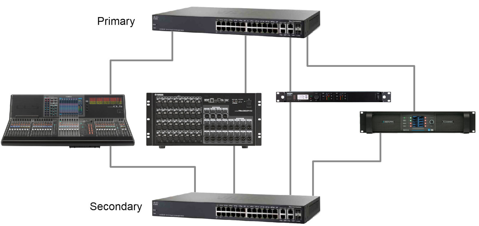
I believe that the days of 100Mbit switches are over anyway, but for the sake of completeness I would like to mention that a switch with 1Gbit ports is of course recommended.
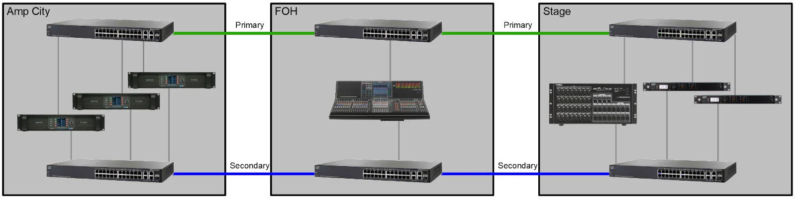
Four Switches (unmanaged)

If the Dante network expands to more than one room, you will want to connect several switches with one another. In my example from the live / theater world, this will usually be the FOH (Front of House) space with the mixer and a rack on the stage for the audio sources, i.e. I / O racks or wireless receivers . Nowadays, power amplifiers also often have a Dante interface and can therefore be integrated directly into the network.
The connection speed is currently 1 Gb/s. A 10Gb port for the uplink between switches doesn't do any harm, but usually doesn't add much value to this simple topology. After all, around 500 audio channels at 48kHz can be transmitted over a 1Gb connection.
Four Switches, managed: Spanning Tree (STP) or Link Aggregation (LAG)

Even if you have full redundancy via the secondary network, it can be advantageous if you can also set up cable redundancy. A defective cable or a dusty fiber optic connector does not lead directly to a complete failure of the primary network, but is automatically intercepted by the redundant cable.
This is particularly important when operating devices that only support the primary Dante network, such as the Audinate Avio adapter or the Dante Virtual Soundcard (DVS).
A managed switch is essential for a redundant connection between switches. Because there can only ever be one active connection, or in other words: there can be no loops in a network. Since a switch outputs the incoming packets to all ports, a loop leads to an endless loop and ultimately to an overloaded network.
Two options for a redundant connection are very easy to set up and are available in almost all switches:
Spanning Tree Protocol (STP)
The Spanning Tree Protocol ensures that only one connection line is active in networks. We will encounter it later when we want to connect several switches redundantly with one another.
But the Spanning Tree Protocol (STP) can also be activated in this simplest form of a double connection between two switches. One of the two connections is then automatically blocked so that only one link is active. If the active line fails, the second line is activated. Everything automatically and without the risk of a loop. And with the STP, different cable types can also be used or mixed, i.e. Cat and fiber optic connections.
Even if one always speaks of Spanning Tree colloquially, one actually means its successor Rapid Spanning Tree (RSTP) nowadays. As the name suggests, this is significantly faster when restructuring in the event of a change. While with the old STP it took more than 30 seconds to open the redundant connection, the RSTP only needs a few seconds.
Link Aggregation Group (LAG)
Several ports can be connected to one logical port on a switch. At Cisco this is called the Link Aggregation Group (LAG), at HP it is also called a trunk. The whole thing has two major advantages: in the event of a connection failure on one of the lines, the remaining lines take over automatically. In addition, the network traffic is distributed over the active lines. Instead of 1Gb/s, with two lines we get approximately 2Gb/s between the switches involved.
However, there is a small restriction: all connections within a LAG must have the same speed and be of the same type, i.e. 1Gb Cat or 1Gb fiber.
Both protocols have one thing in common: when the connection is broken on the active line, there is an audio dropout in the primary Dante network. It is therefore not a substitute for the parallel secondary network, which creates an uninterrupted audio connection.
In my attempts without a secondary connection, the audible loss of sound was between 0.5 and 9 seconds for both protocols (STP or RSTP and LAG). This is not uninterrupted, but still better than doing without all devices for the rest of the event that are only available in the primary network.
Daisy Chain (unmanaged)
With more than two switches we end up with a certain daisy chain cabling when using unmanaged switches. Connections between the primary and secondary network are prohibited. Ring topology is also not permitted.
Nonetheless, this is a very common structure, as there are no special requirements for the switches and no IT specialist knowledge is necessary.
Triangle (managed: Spanning Tree / RSTP)
The Spanning Tree Protocol has the advantage that more connections than necessary can be made between switches. In the event of a cable problem, the network automatically realigns itself and all switches and devices can still be used.
Before using this topology, however, it is essential to check the configuration of all switches. Only if STP is activated everywhere (both globally and per port) can you intentionally insert loops.
However, STP is not quite as clever as one might naively assume. In a switch ring, the shortest connection is not simply used to transmit data packets. Unfortunately, one of the connections is interrupted so that there is no longer a forbidden loop.

In our example, the connection between Switch 3 and 5 and the connection between Switch 4 and 6 are interrupted (dashed lines). Data packets between devices on switch 3 and switch 5 always go via switch 1.
Depending on the structure, it can make sense to tell the network exactly which redundant connection should be interrupted during normal operation. For example, it would be disadvantageous if the connection between FOH and stage (switch 1 and 3) were interrupted and all traffic would always have to go through switch 5.
The so-called root bridge is important for setting up the spanning tree. The network automatically selects a root bridge from all switches. The decisive factor here is the Root Priority parameter, which can be changed. If all switches have the same priority (the default is usually the value 32768, see screenshot on the right), the choice is based on the lowest MAC address.
If you check in any switch whether STP is active, you should briefly draw up a sketch of the flow of the audio packets and change the root priority of the switch that is expected to be in the middle of the flow. Incidentally, the choice of the root bridge wins the lowest priority value, and the values must be a multiple of 4096. If you change the value for a switch to 4096, it will win over all others with the default value of 32768 and take on the role of the root bridge.

The remaining switches then select the route with the lowest costs to the root bridge. In the case of our triangle (with switch 1 as root) and with identical 1Gb speeds for all connections, switches 3 and 5 will activate the direct path to switch 1. The path between switch 3 and 5 therefore remains unused and is blocked.
Ring Topology
Once Dante has established itself in a house, you will soon want to integrate a Dante device in every room. The number of switches increases accordingly.
Of course, a square and larger rings can be built from the triangle. As long as the ring is closed and STP is active, the cable redundancy is retained. And a ring is quite easy to set up, since most current switches have 2-4 uplink ports as standard. So you don't need an additional switch as a distributor.
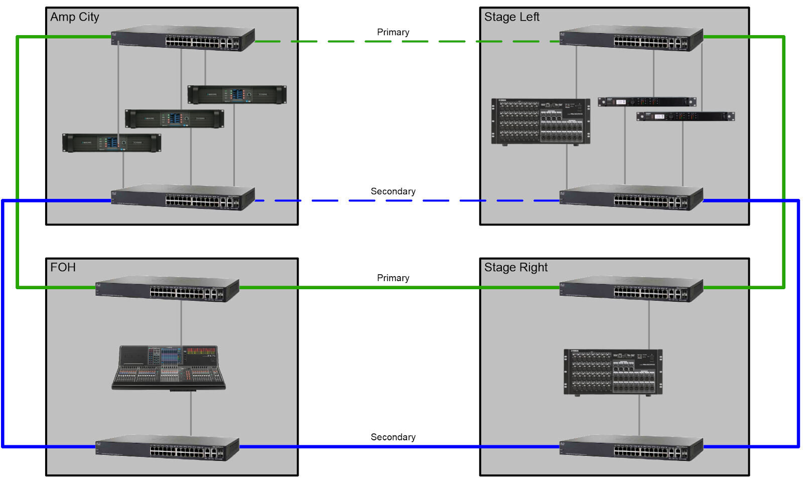
As mentioned before in a spanning tree situation with redundant links, there will automatically be one connection that is blocked by STP. If you have a clear opinion which one would make the most sense, you can influence the STP structure by increasing the path cost for one link. In the above example there will probably not be much traffic between stage left and amps anyway, so this could be considered as the redundant link.
Star Topology (unmanaged)
Usually, however, it is more practical if you set up the Dante network in a star shape. This makes it easy to add another room later. In addition, each room can be switched off without the other rooms losing their connection to one another.
For now we will stick to the relatively uncomplicated structure with unmanaged switches. However, I would like to make a small note: even if no managed switch functions are required for this setup, it of course makes sense to still provide switches that can handle all of these functions as presented here (STP, LAG, Trunk, VLAN), in order to be able to refer to it later if necessary. In addition, the day will come when you want to use multicast flows in the Dante world and possibly functions such as IGMP snooping. Nevertheless, the following unmanaged topology can serve as a start without having to familiarize yourself with switch configurations.
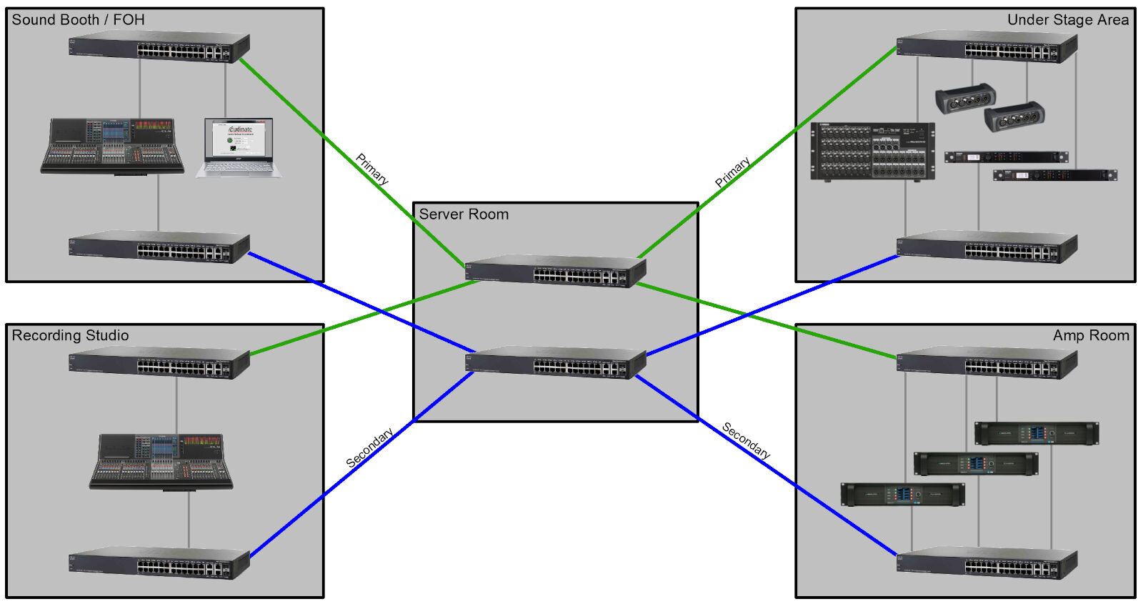
The entire audio traffic runs through the central switches 1 (for the primary network) and 2 (for the secondary network). These switches should be designed to be fail-safe. While switching off individual rooms does not affect the other connections, the central switches must always be switched on so that Dante signals can flow through the house.
Star Topology (managed: VLAN, trunk, RSTP / MSTP)
And now we are slowly coming to the topologies that I enjoy most, but which are very time-consuming due to their complexity. The time required to set up and test is far greater than with a simple (i.e. split) Dante network. Such a mixed network makes more sense for permanent installations such as theaters, operas and concert halls.
For time-critical setups for one-off live events, I would not recommend mixing the primary and secondary network as shown here, because things can go wrong and you can easily impair the redundancy of the two networks.
In terms of cabling, it is hardly any different from the previous unmanaged example. But it has one big advantage:
All switches are now connected redundantly. Any cable connection can fail, but the switch will still be connected again after a few seconds thanks to the Spanning Tree Protocol. And for this big step, on the hardware side, only a few short patch cables are actually needed between the primary and secondary switch in the same room.

In addition to the STP or RSTP, you always have to create VLANs for such a structure and assign all ports to them manually. The separation of the primary and secondary networks is still given through the use of VLANs. All connections between switches must be designed as a trunk so that all VLANs can be transmitted over a single cable. Normally, the traffic will go separate ways as shown above. But in the event of an accident, all data can also be sent over the remaining connection if necessary.
This is particularly important if devices are also in use without a secondary connection, such as the small AVIO adapter* or a converter from Neutrik*. Likewise, the Dante Virtual Soundcard can only be connected to the primary network (you can read more about the Dante Virtual Soundcard in this blog-article). It is correspondingly advantageous if we not only use the secondary network as a buffer, but also provide the primary network itself with certain redundancies.
And as the icing on the cake, all switches are now connected to one another in a network and can be configured very conveniently via a single access. Additional VLANs, for example a control network, can be integrated quickly and flexibly.
The other side of the coin: a well thought-out configuration is required. The configuration of ten switches not only takes time, it is also dangerous. As a network administrator, work doesn't stop when all devices can communicate with each other. In redundant structures such as in a Dante network, it is much more a matter of carefully checking and controlling which data flows through which connections.
If the simple spanning tree (RSTP) is used, there is only one root bridge per network, across all VLANs. Even if this is configured carefully (for example on the central primary switch), it can happen for the remote secondary switches that they choose a route via the primary switch and not use the actual connection to the central secondary switch. The actual purpose of the secondary network, namely the uninterrupted audio connection in the event of a network problem, is no longer given.
Whenever you connect the primary and secondary network at any point, you are well advised to set up the Multiple Spanning Tree Protocol (MSTP). As the name suggests, several instances of the STP can be set up in a network. We can configure an independent structure for our primary and secondary Dante VLAN, with a different root bridge.
When using trunk lines for several VLANs, one must always keep in mind that the bandwidth doubles if the primary and secondary network are transmitted over one line in the event of an accident. The maximum number of channels is halved in mixed networks.
I would no longer operate a mixed network without constantly keeping an eye on all switches, their uplinks and parameters - i.e. having network monitoring running in the background. I have explained some examples in my blog article on PRTG, and you will also gain insight into the network topologies used there.
Mesh = mixed topology
Of course, you can also deviate from the “pure” ring or star topology with the switch connections and add your own connections. With a star, for example, it can make sense to also connect certain rooms with one another. Then the connection would still be available even if the central switches fail completely.
Conclusion
I hope I was able to show you a few scenarios of how Dante devices can be networked with one another in larger houses. Regardless of which topology you try, it is ultimately always important that you try the case of an accident and check whether the audio connection remains audible or has dropouts. In a professional environment, every component in the network should be able to fail, both a switch and a cable, without the viewer noticing anything.
By the way, I primarily use the Cisco SG-350* and its successor Cisco CBS-350* switch in my little “laboratory” at home. On the one hand, it offers exactly what a modern switch has to be able to do for Dante applications and can be operated both via the command line and via a web browser. On the other hand, it is already used in many theater projects and I can prepare and follow up the switch configurations for each project. In the version with 8 ports it is quite affordable and from my point of view the perfect managed switch to start with.
With this in mind, have fun trying it out!
* Affiliate Link
More Network / Dante articles:
Network-Monitoring (PRTG): Benefits and Examples
Comparison: Cisco SG250 vs SG350